
Mass flow Ṁ and volumetric flow Q
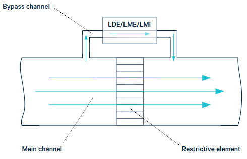
A restrictive element in the main channel defines the relationship between gas flow F and differential pressure (∆P):
F = ƒ (∆P)
Typically, the gas flow F is measured as mass flow Ṁ [mass per time]. If needed, volumetric flow Q [volume per time] can be derived from mass flow.
The volumetric flow is equal to the mass flow over gas density:
Q = Ṁ / ρ;
From the Ideal Gas Law, the gas density can be found as:
ρ = (MP) / (RT)
Standard volumetric flow Qs
Standard volumetric flow is a volumetric flow defined at “standard” tem–
perature (Tstd) and “standard” pressure (Pstd). Different manufacturers
refer to different standards (e.g., Tstd = 21.1 °C or 70 °F, Pstd = 101.3 kPa or
14.7 psia).
Commonly used units for standard volumetric flow are “standard liters per
minute [slm]” or “standard cubic centimetres per minute [SCCM]”.
For a given gas, volumetric flow at non-standard temperature (T) and
non-standard pressure (P) can be found as:
Q = Qs (Ps/P) (T/Ts)
Laminar and orifice-like flow restrictive elements
Ideally, a pressure drop on a laminar restrictive element increases
linearly with the flow, while a pressure drop on an orifice increases
quadraticly (Figure 2).
While the production cost of a laminar restrictive element is higher, it
has two advantages in comparison to an orifice-like restrictor:
– wider flow measurement range (∆F2 > ∆F1);
– increased sensitivity around zero flow.
In reality, a flow restrictive element is a combination of the two restric–
tors described above; either the linear or quadratic pressure-from-flow
characteristic dominates.
Definitions:
∆P: pressure drop on a flow-restrictive element;
Ṁ: mass flow;
Q: volumetric flow;
ρ: gas density;
M: molar mass;
P: pressure;
R: gas constant;
T: absolute temperature
Barometric correction
For any thermo-anemometer type differential pressure sensor, including
the LDE/LME/LMI, output signal Vout is proportional to gas density ρ.
That is why barometric correction is required for ∆P measurements.
Vout ~ ∆P · ρ (1)
From Poiseuille’s equation, pressure drop on a laminar restrictor ∆P is
proportional to mass flow Ṁ and inversely proportional to gas density ρ:
∆P ~ [μL/D4] · Ṁ · 1/ρ (2)
From (1) and (2)
Vout ~ [μL/D4] · Ṁ (3)
From Bernoulli’s equation pressure drop on an orifice-like restrictor ∆P
is proportional to mass flow in power of two Ṁ2 and inversely proportio–
nal to gas density ρ:
∆P ~ [1/D4] · Ṁ2 · 1/ρ (4)
From (1) and (4)
Vout ~ [1/D4] · Ṁ2 (5)
From (3) and (5) follows that the LDE/LME/LMI sensors intrinsically
require no barometric correction for mass flow measurements.
Definitions:
∆P: pressure drop on a flow-restrictive element;
Ṁ: mass flow;
ρ: gas density;
μ: gas viscosity;
L: length of a flow-restrictive element;
D: inner diameter of a flow-restrictive element
Temperature compensation
The LDE/LME/LMI families feature an embedded temperature sensor.
Depending on the application, the LDE/LME/LMI sensor can be fully tem–
perature compensated at the factory either for mass flow or for differential
pressure.
Bypass flow
A main channel restrictor’s pressure/flow characteristic is usually
defined without considering bypass flow and bypass flow variation from
sample to sample. Thus, a smaller flow in the bypass results in better
bypass/main channel split ratio and therefore higher accuracy. The
amount of flow in the bypass channel is defined by a sensor’s pneumatic
impedance Zp [pressure per flow]. The higher the impedance, the lower
the bypass flow. The pneumatic impedance of the LDE/LME/LMI families
can be found in a range from 10,000s to 100,000s (Pa · s) / (ml).
For example, if a 250 Pa LDE sensor’s pneumatic impedance Zp is
25,000 (Pa · s) / (ml), then the bypass flow at nominal pressure F250 can
be found as
F250 = ∆P / Zp = 250 Pa / 25,000 (Pa · s) / (ml) = 0.01 mL/s.
LDE/LME/LMI features suitable for flow metering
– No temperature or barometric compensation is needed for mass flow
application.
– The highest-in-class pneumatic impedance guarantees the highest im-
munity to contamination and the highest bypass/main channel split ratio.
– An embedded temperature sensor can be read out by the user for
temperature correction in volumetric flow application (see paragraph 1.2).
– Linearized sensor output is convenient for expanding pressure and
flow dynamic range by “cascading” the LDE/LME/LMI sensors. For
example, a 50 Pa sensor can be read out in parallel with a 500 Pa
sensor virtually without data irregularities when transitioning from
sensor to sensor.


